When redesigning the original JAMR-250 robot, I wanted to address 4 specific challenges that we encountered leading up to the competition:
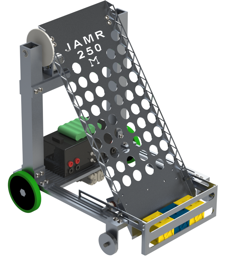
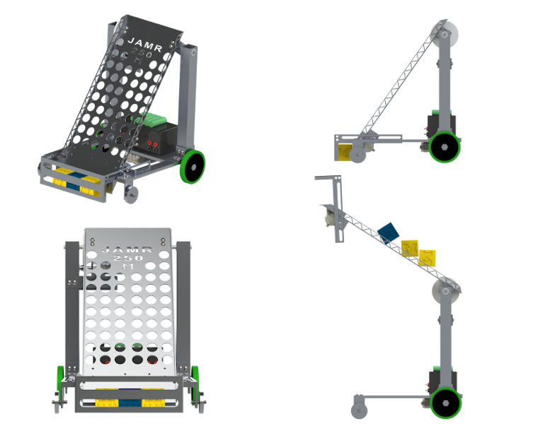
- Rotating within the small playfield oftentimes required multi-point turns, creating less consistency while turning and eating up more time. This was due to the large footprint of the RMP.
- The drivetrain spring pins loosened over time, requiring continuous repairs and modifications. Coupled with the high center of mass, this made traversing over steep slopes quite difficult.
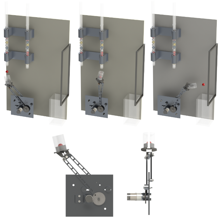
- Due to the design of the ramp and grabber, our robot would have to turn 180 degrees and back up into the goal baskets in order to deposit cubes. This adds more complexity and uses more time.
- The design of the grabber was very complex and could be simplified down to reduce the number of components.
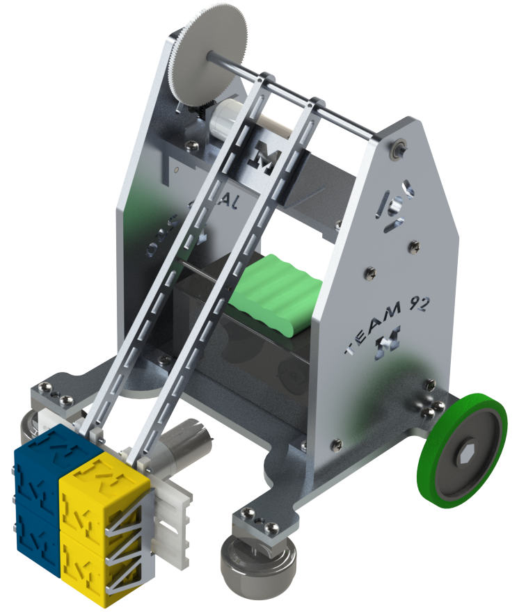
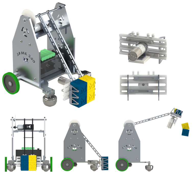
The final assembly mass is 3.8 kg, mostly due to more mass kept on the baseplate. Relative to the center of the left rear wheel, the COM (length, width, height) is located at (3.76in, 4.48in, 2.06in) - a ~45% reduction in the COM height. Lowering the center of mass makes it much easier to move over high inclines, and keeping more weight above the wheels has the added benefit of adding more friction and better traction. The final robot fits in a 7.5 in x 8.96 in footprint, measuring 10.25 in tall.
The use of ball casters for the front wheels greatly improves the mobility of the robot, especially in turning.
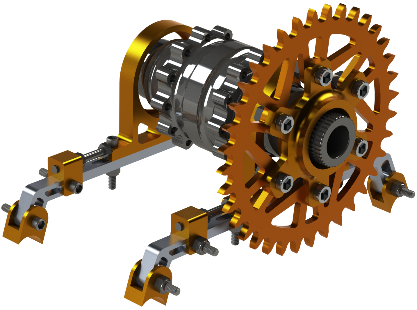
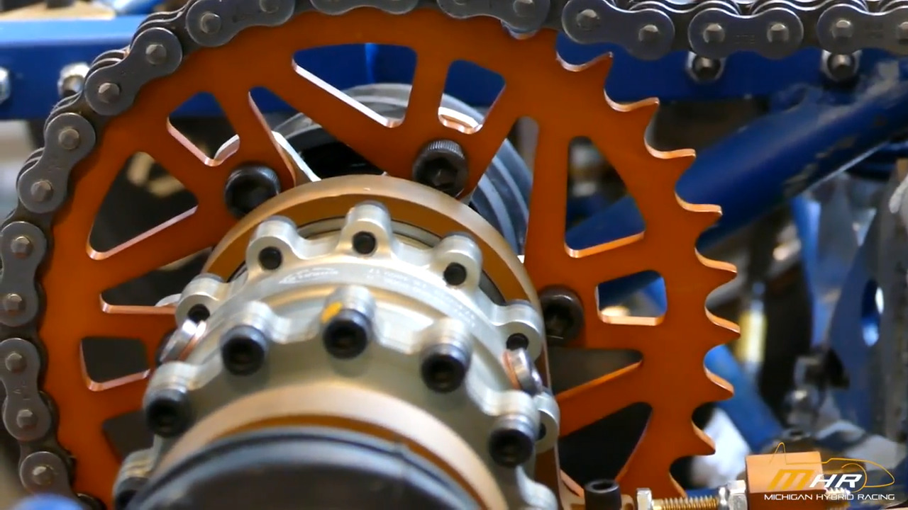
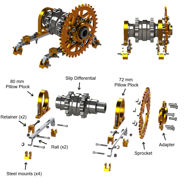
The double gearbox rear wheel drivetrain was replaced by two pololu metal motors with more reliable meshing with the axles.
The pneumatic grasper allows for the robot to easily grab cubes and deposit them without needing to rotate 180 degrees. This saves extra time per trip and reduces the complexity. In addition, the pneumatic assembly is more stable and better constrains degrees of freedom.